In this post we are going to explore two case study: the first one is dedicated to resolving issues with die maintenance for a component of automotive sector, while the second one regards the optimization of set up parameters for a component of small domestic appliances.
This post is part of a series in which we explain the importance of simulation for HPDC (High Pressure Die Casting) through the presentation of real life cases.
You can find a full list of discussed topics in our first post on the subject, by clicking here.
CASE STUDY DIE MAINTENANCE: automotive industry
The product we are going to analyze in this post is a steering lock housing assembly for automotive industry.
The critical part was the upper cover of the steering block assembly, containing an electronic card. The part itself was not flawed at first, but soon the signs of mold erosion started to show up. The erosion of the mold left distinctive marks on the surface of the component: these irregular dark spots were the sign of die wear.
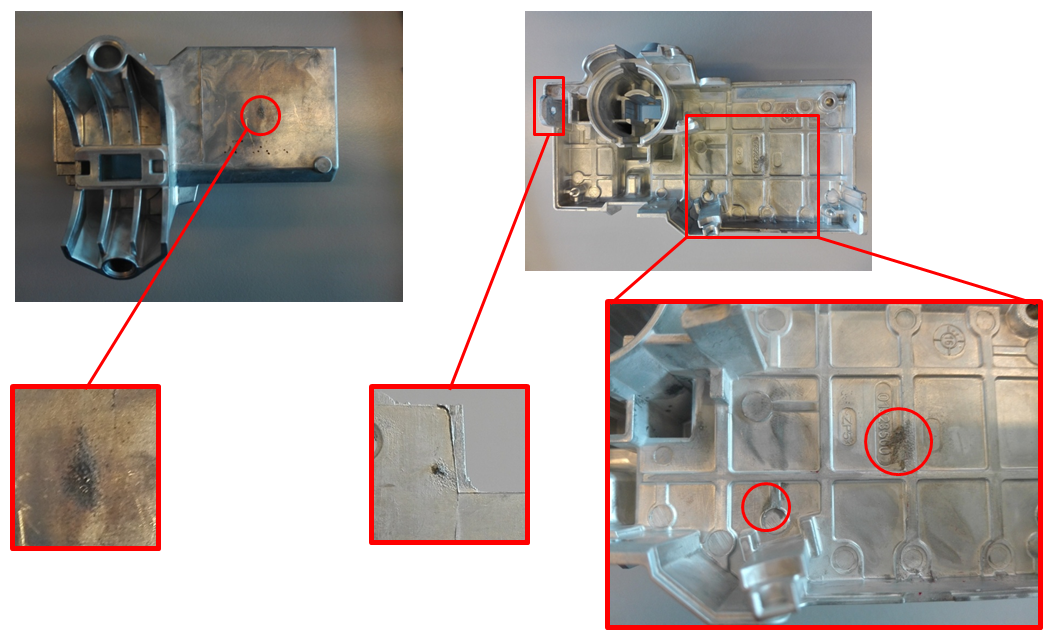
The identified die wear was caused by the high speed of flow during the filling phase and by the specific geometry of the part. The consequences of poor die maintenance are rather severe as they can bring on a malfunctioning of the part, caused by surface spurs resulting from die wear, in addition to increasing the need for maintenance work. In order to solve the problem, a simulation of the filling process was run.
OBJECTIVE AND PHASES OF THE SIMULATION
The objective of the simulation was to identify opportunities for slowing down or eliminating erosion on an existing die: to achieve the wanted result, our engineering department run an analysis of alternative feeder solutions.
The first step was to identify the cause of erosion: erosion is caused by the development and non-stationary implosion of alloy bubbles against the surface of the die. Due to high speeds of the flow through the narrow ducts in proximity of feeder, the pressure falls below the vapor pressure of the alloy, causing it to evaporate instantaneously.
Subsequently, the alloy enters the die with a larger cross section than the feeders, causing an expansion that reduces the speed of the flow. The pressure rises rapidly causing the implosion of vapor bubbles and freeing up energy. This entire process is called cavitation and is the main cause of wear to the internal surface of the die.
RESULTS
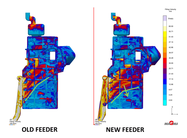
The filling velocity field represents the speed of the flow when it initially enters the control volume.
Since cavitation is a non-stationary process that takes place in the first phase of filling, which is also the phase of highest instability, the study of filling velocity field represent the highest opportunity to identify the critical areas.
As the following images show, the new geometry positively influences the expansion of the flow, mitigating the velocity gradients along the green line.
Internal part of the housing
The area with largest cavitation is in the center of the field, where the green line demarcates the separation between two areas with different speeds. Exactly in this area, because the flow slows down and pressure increases, the alloy bubbles implode and damage the die.
With the new feeder duct the green line is moved generating a broadening of flow diffusion. This broadening should shift the cavitation area and reduce the risk of cavitation because of the lower speed gradient in the critical area of the die.
External part of the housing
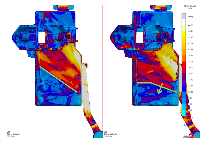
The green line moved on the fixed side of the die as well, broadening the diffusion and diminishing the transversal speed gradient.
In conclusion, the use of simulation allowed to identify the critical area in which cavitation was occurring and to design a broaden flow to shift cavitation, preventing wear of the die and reducing the need of die maintenance.
We will now move on with the next case study, which focuses on small domestic appliances and set up parameters optimization.
CASE STUDY OPTIMIZATION OF SET UP PARAMETERS: small domestic appliances
The subject of our second case study is a chrome plated handle. The product is a component for a pad type coffee machine: in this case there was not a problem to fix, but it was necessary to identify the correct filling of the die to optimize the production.
In order to achieve a high level of esthetical quality, the die has to be maintained at very high temperatures: high temperature in the die reduces alloy cooling during the filling phase, reducing flow marks. However, high temperatures implies longer cooling time: as a consequence, the cycle time expands because of the prolonged solidifying phase of the part. Therefore, it is necessary to establish an operating temperature range that allows a high quality level while keeping the cycle time as low as possible, to increase productivity.
Once identified, the die casting conditioning parameters can be set to keep the die within the range. These conditioning parameters are entry temperature and the type of coolant.
OBJECTIVES AND PHASES OF THE SIMULATION
The objective of the simulation is to estimate the change in surface quality and cycle time at the varying of die temperatures.
Die temperature depends on two factors: the geometry of the conditioning circuit, defined in engineering phase, and the temperature and nature of the coolant applied in production phase.
In the simulation, a homogeneous die temperature was imposed in proximity of the cavity. Surface quality has been determined by the average value of the alloy temperature at the end of the filling phase, whereas the production cycle has been derived from the necessary time for the component to solidify and cool to a temperature of 340°C.
The evolution of the two quantities has been calculated across a series of simulations in which the temperature was made variable.
RESULTS
The following graph clearly indicates the results of the series of simulations. Technically, this is not an optimization analysis because the two monotonously increasing curves do not allow to find an absolute minimum or maximum: it can be considered as a tradeoff analysis to define the optimal temperature range.
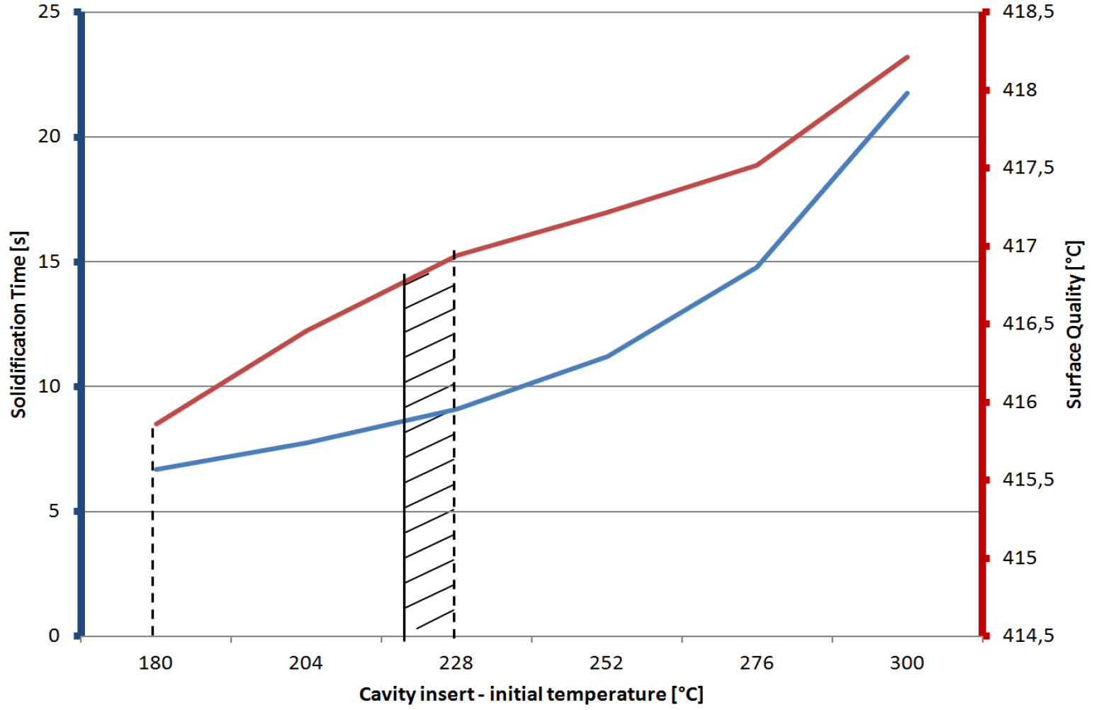
The 180 - 228°C temperature range is where the surface quality curve grows most significantly, while the product cycle time stays fairly constant before increasing almost exponentially.
For these reasons we choose the range within bandwidth of about 10°C, placed at the extreme right of the interval (218°C < T < 228°C).
In this case, simulation of the component has helped determine the ideal die temperature range to obtain the required surface quality, guiding the setting of entry temperature and the choice of the coolant.
In conclusion, throughout this series of post we have seen different applications of simulation for die casting: scrap reduction, optimization of esthetical quality, improvement of mechanical characteristics, improved die maintenance and optimization of set up parameters are only some of the many advantages offered by the use of this technology.
To always be up-to-date with the newest techniques for zinc die casting, subscribe to our blog.